


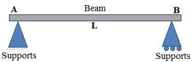
SIMPLY SUPPORTED BEAM :-
A simply supported beam is a type of beam that has pinned supported one end and roller support at the other end. Depending on the load applied, it undergoes shearing and bending. It is the one of the simplest structural elements in existence.
A simply supported beam is a type of beam that has pinned supported one end and roller support at the other end. Depending on the load applied, it undergoes shearing and bending. It is the one of the simplest structural elements in existence.
(UDL AND POINT LOAD CONDITIONS)

Stress in a bending beam can be expressed as :-
σ = y M / I
whereσ = stress (Pa (N/m2), N/mm2, psi)
y = distance to point from neutral axis (m, mm, in)
M = bending moment (Nm, lb in)
I = moment of Inertia (m4, mm4, in4)
Beam Supported at Both Ends - Uniform continuous Distributed Load

Maximum moment in a beam with uniform load supported at both ends:
Mmax = W L2 / 8
where
Mmax = maximum moment (Nm, lb in)
q = uniform load per length unit of beam (N/m, N/mm, lb/in)
L = length of beam (m, mm, in)
Moment in position x:
Mx = qx (L - x) / 2
where
Mx = moment in position x (Nm, lb in)
x = distance from end (m, mm, in)
Maximum Stress
Maximum stress in a beam with uniform load supported at both ends:
σmax = ymax q L2 / (8 I)
where
σmax= maximum stress (Pa (N/m2), N/mm2, psi)
ymax = distance to extreme point from neutral axis (m, mm, in)
1 N/m2 = 1x10⁻⁶ N/mm2 = 1 Pa = 1.4504x10⁻⁴ psi
1 psi (lb/in2) = 144 psf (lbf/ft2) = 6,894.8 Pa (N/m2) = 6.895x10⁻³ N/mm2
Maximum deflection:
yM = - (5/384) [q.L3/EI]where
Ym = maximum deflection (m, mm, in)
E = Modulus of Elasticity (Pa (N/m2), N/mm2, psi)
Note! - deflection is often the limit factor in beam design. For some applications
beams must be stronger than required by maximum loads, to avoid unacceptable deflections.
Forces acting on the ends:
R1 = R2
= q L / 2
where
R = reaction force (N, lb)
Maximum slop :-
θ = θA = -W.L2/24EI
Example - Beam with Uniform Load :-
The maximum stress in a "W 12 x 35" Steel Wide Flange beam, 100 inches long, moment of inertia 285 in4, modulus of elasticity 29000000 psi, with uniform load 100 lb/in can be calculated as
σmax = ymax q L2 / (8 I)
= (6.25 in) (100 lb/in) (100 in)2 / (8 (285 in4))
= 2741 (lb/in2, psi)
The maximum deflection can be calculated as
δmax = 5 q L4 / (E I 384)
= 5 (100 lb/in) (100 in)4 / ((29000000 lb/in2) (285 in4) 384 = 0.016 in
Beam Supported at Both Ends - Load at Center

Maximum moment in a beam with centercload supported at both ends:
Mmax = F L / 4
Maximum Stress
Maximum stress in a beam with single center load supported at both ends:
σmax = ymax F L / (4 I)
where
F = load (N, lb)
Maximum deflection can be expressed as
δmax = F L3 / (48 E I)
Forces acting on the ends:
R1 = R2
= F / 2
Thanks you.. Next topic .... Click here.
How to beam fail :-


0 Comments