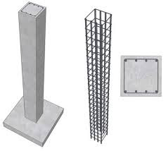
Design of Column
 |
| Column design |
Working Stress Method<
Slenderness ratio (λ)

If λ > 12 then the column is long.
Load carrying capacity for short column
where, AC = Area of concrete, 
σSC Stress in compression steel
σCC Stress in concrete
Ag Total gross cross-sectional area
ASC Area of compression steel
Load carrying capacity for long column
where,
Cr = Reduction factor

where, leff = Effective length of column
B = Least lateral dimension
imin = Least radius of gyration and 

where, l = Moment of inertia and A = Cross-sectional area
Effective length of column
Effective length of Compression Members


Column with helical reinforcement
Strength of the column is increased by 5%
Longitudinal reinforcement
(a) Minimum area of steel = 0.8% of the gross area of column
(b) Maximum area of steel
(i) When bars are not lapped Amax = 6% of the gross area of column
(ii) When bars are lapped Amax = 4% of the gross area of column
Minimum number of bars for reinforcement
For rectangular column 4
For circular column 6
Minimum diameter of bar = 12 mm
Maximum distance between longitudinal bar = 300 mm
Pedestal: It is a short length whose effective length is not more than 3 times of lest lateral dimension.
Transverse reinforcement (Ties)

where  dia of main logitudnal bar
φ = dia of bar for transverse reinforcement
Pitch (p)

where, φmin = minimum dia of main longitudinal bar
Helical reinforcement
(i) Diameters of helical reinforcement is selected such that

(ii) Pitch of helical reinforcement: (p)

where,
dC = Core diameter = dg – 2 × clear cover to helical reinforcement
AG = Gross area 
dg = Gross diameter
Vh = Volume of helical reinforcement in unit length of column
φh = Diameter of steel bar forming the helix


dh = centre to centre dia of helix
= dg – 2 clear cover - φh
φh = diameter of the steel bar forming the helix

Some others IS recommendations
(a) Slenderness limit
- Unsupported length between end restrains
 60 times least lateral dimension.
 - If in any given plane one end of column is unrestrained than its unsupported lengthAll column should be designed for a minimum eccentricity of

Limit state method
- Slenderness ratio (λ)
if
λ<12 Short column
- Eccentricity

If then it is a short axially loaded column.
where, Pu = axial load on the column - Short axially loaded column with helical reinforcement

- Some others IS code Recommendations

(a) Slenderness limit
(i) Unsupported length between end restrains  60 times least lateral dimension.
(ii) If in any given plane one end of column is unrestrained than its unsupported length 

(b) All column should be designed for a minimum eccentricity of

Concentrically Loaded Columns
Where e = 0, i.e., the column is truly axially loaded.
This formula is also used for member subjected to combined axial load and bi- axial bending and also used when e > 0.05 D.
*****


0 Comments